msbte.org.in Summer Examination 22326 & 17422 Question Paper 2019 : Maharashtra State Board Technical Education
Organisation : Maharashtra State Board Technical Education
Exam: Summer Examination 2019
Code Number : 22326/17422
Document Type : Question Paper
Year : 2019
Website : https://msbte.org.in/portal/question-paper-search/
MSBTE Summer Examination 22326 & 17422 Question Paper
Download Question Paper of Summer Examination 2019 Sample Question is now available in the official website of Board of Maharashtra State Board Technical Education.
Related : MSBTE Summer Examination 2019 Question Paper : www.pdfquestion.in/34378.html
Instructions
(1) All Questions are compulsory.
(2) Answer each next main Question on a new page.
(3) Illustrate your answers with neat sketches wherever necessary.
(4) Figures to the right indicate full marks.
(5) Assume suitable data, if necessary.
(6) Use of Non-programmable Electronic Pocket Calculator is permissible.
(7) Mobile Phone, Pager and any other Electronic Communication devices are not permissible in Examination Hall.
(8) Use of steam tables, logarithmic, Mollier’s chart is permitted.
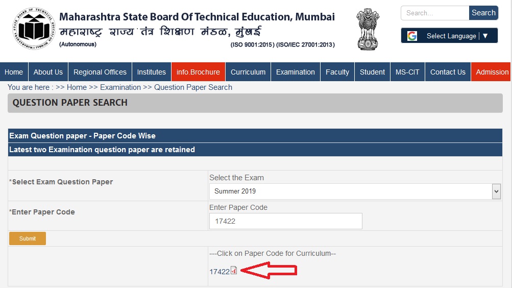
Download Question Paper :
22326 :
https://www.pdfquestion.in/uploads/pdf2019/34391-22326.pdf
17422 :
https://www.pdfquestion.in/uploads/pdf2019/34391-17422.pdf
Subject Code : 22326
21819
Time/ MM : 3 Hours / 70 Marks
1. Attempt any FIVE of the following : 10
(a) Give the applications of IGBT.
(b) What is the need of UPS ?
(c) Draw a neat circuit diagram of class F commutation.
(d) Define :
(i) Firing angle
(ii) Conduction angle
(e) How GTO is advantages over SCR ?
(f) State the main difference between PUT & UJT.
(g) Write the function of Freewheeling diode.
2. Attempt any THREE of the following : 12
(a) Describe triggering of SCR using UJT relaxation oscillator.
(b) Draw the I-V characteristics of power transistor. Show all regions.
(c) With neat circuit diagram explain working of emergency light system.
(d) Compare SCR & TRIAC (any four).
3. Attempt any THREE of the following : 12
(a) Explain with neat circuit diagram operation of temperature controller using SCR.
(b) Draw the circuit diagram of class-D commutation & explain its working.
(c) With neat constructional diagram write operating principle of PUT.
(d) Explain with circuit diagram of 1? mid-point controlled rectifier with R-load.
4.Attempt any THREE of the following : 12
(a) Draw a neat labelled I-V characteristics of SCR.
Define :
(i) Latching
(ii) Holding current
(b) Differentiate between Natural and Forced commutation (any four).
(c) Draw construction of IGBT. State any two applications of it.
(d) Explain with circuit diagram the working of 1? halfwave controlled rectifier with R-L load.
(e) Draw a suitable circuit to control the speed of the motor using TRIAC and also give its operation.
5. Attempt any TWO of the following : 12
(a) Draw a structure of TRIAC with doping levels. Write operating principle and give two applications of it.
(b) Draw the circuit diagram & waveforms of class A commutation. Explain its working.
(c) Draw & explain the working of 1? mid-point controlled rectifier with RL-Load. Also Draw input-output waveforms of it.
6. Attempt any TWO of the following : 12
(a) Draw full bridge & half bridge configuration with common cathode.
(b) Explain working of AC circuit breaker using SCR with circuit diagram.
(c) Draw symbol & V-I characteristics of
(i) LASCR
(ii) DIAC &
(iii) TRIAC
Subject Code : 17422
Time/ MM : 4 Hours / 100 Marks
Instructions :
(1) All Questions are compulsory.
(2) Answer each next main Question on a new page.
(3) Illustrate your answers with neat sketches wherever necessary.
(4) Figures to the right indicate full marks.
(5) Use of Non-programmable Electronic Pocket Calculator is permissible.
(6) Mobile Phone, Pager and any other Electronic Communication devices are not permissible in Examination Hall.
1. (A) Attempt any SIX : 6 ? 2 = 12
(a) Explain the condition for no tension or zero stress at extreme fiber.
(b) State the middle third rule.
(c) State the relation between slope and deflection.
(d) State the values of maximum slope and deflection at free end of a cantilever that carries point load at free end.
(e) State advantages of fixed beam.
(f) Define carryover factor.
(g) Define distribution factor.
(h) Difference between any two points between Perfect and Imperfect frame.
(i) Define Redundant Frame.
(B) Attempt any TWO : 2 ? 4 = 8
(a) Calculate limit of eccentricity for rectangular section having width ‘b’ and depth ‘d’ and show it on sketch.
(b) Write step-by-step procedure for determination of minimum and maximum stresses developed at the base of section.
(c) A solid circular column of diameter 250 mm carries an axial load ‘W’ kN and a load of 200 kN at an eccentricity of 150 mm. Calculate minimum value of ‘W’ so as to avoid the tensile stresses at base.
2. Attempt any FOUR : 4 ? 4 = 16
(a) State the slope and deflection at the ends of simply supported beam of span ‘L’ carrying a udl of w/unit length over entire span.
(b) Write the equation for slope and deflection at free end for a cantilever beam having u.d.l. over entire span and meaning of terms used in it.
(c) Explain step-by-step procedure of Macaulay’s method for finding slope and deflection equation.
(d) Find the maximum deflection for a simply supported beam of 6 m span carrying a point load of 20 kN at 2 m from left support as shown in fig. 1. Take E = 2 ? 106 N/mm2, I = 2 ? 107 mm4.
(e) Explain principle of superposition with respect to fixed beam.
(f) A fixed beam of span 6 m carries an udl of 15 kN/m over entire span. Find fixed end moment from first principle and draw B.M.D.
3. Attempt any FOUR : 4 ? 4 = 16
(a) A rectangular column is 200 mm wide and 100 mm thick. It carries a load of 180 kN at an eccentricity of 100 mm in the plane bisecting thickness. Find the maximum and minimum intensities of stress in section.
(b) Determine distribution factor at continuity for a continuous beam ABCD which is fixed at A and simply supported at B, C and D. Take AB = 6 m, BC = 3 m and CD = 2 m. If M.I. for span is IAB = 3I, IBC = 2I & ICD = 1I
(c) A propped cantilever AB of span 4.2 m is fixed at A and propped at B, carrying UDL of 20 kN/m. Using clapeyron’s theorem, calculate support moment and draw BMD.
(d) State the method of analysis of frame.
(e) Differentiate between symmetrical and unsymmetrical portal frame.
(f) State Clapeyron’s theorem of three moments and meaning of each terms involved.
4. Attempt any TWO : 8 ? 2 = 16
(a) A circular chimney has external diameter 60% more than internal diameter. The height of chimney is 30 m and is subjected to a horizontal wind pressure of 1.70 kN/m2. Find out the diameter of chimney so as to avoid tension at the base of chimney and also draw stress distribution diagram unit wt of chimney material is 19 kN/m3 and C = 0.60.
(b) A fixed beam 5 m long carries a load of 60 kN at 2m from left end. Calculate the fixed end moments, net B.M. under the load and end reactions.
(c) A C.I. hollow circular column section has external diameter 250 mm and internal diameter 200 mm. It is subjected to a vertical load of 25 kN at adistance of 350 mm from the vertical axis of column. Calculate the maximum and minimum stresses at the base of the column and draw stress diagram.
5. Attempt any TWO : 8 ? 2 = 16
(a) A continuous beam ABC is simply-supported at A, B and C such that AB = BC = 2 m. Span AB carries a u.d.l. of 50 kN/m. From A to B, Span BC carries a point load of 40 kN at 0.5 m from C. Draw bending moment diagram and calculate support reactions. Use Clapeyron’s theorem of moments.
(b) A propped cantilever of span 6 m carries a u.d.l. of 10 kN/m over the entire span. Prop is free end. Calculate the fixed end moments using Clapeyron’s theorem of three moments. Also draw SFD & BMD.
(c) A continuous beam ABCD is loaded as shown in fig. No. 2. using moment distribution method. Find the support moments and draw B.M.D.
6. Attempt any TWO : 8 ? 2 = 16
(a) Find out the forces in the member by method of section.
(b) Find out the forces in the members of a cantilever truss as shown in fig. No. 3.
(c) A truss is loaded as shown in fig. 4 Determine the nature and magnitude of truss forces in the members BE, BG and ED. Use method of joint only.